
1 Introduction
It is often stated that fuel flexibility is a big advantage for Solid Oxide Fuel Cells (SOFCs) in marine applications since the marine industry is not sure which fuel will be widely available in the future. Several fuels can be used in SOFCs due to the high operating temperature. However, it is still unknown which fuel performs best for a marine SOFC power plant, and it might even depend on the application.
The performance of a marine SOFC power plant for several fuels (methane, methanol, diesel, ammonia, and hydrogen) is compared in terms of electrical and thermal efficiency. It is investigated what influence the operational voltage and fuel utilisation of the SOFC have on the efficiencies of the different systems.
| Shortlist | Fuel | Storage Technique |
|
LNG (main fuel of Nautilus) |
Liquified Natural Gas |
Cryogenic -162°C |
| MeOH | Methanol |
Liquid Amb. T |
| FT D | Fischer-Tropsch Diesel |
Liquid Amb. T |
| NH3 | Ammonia |
Cryogenic -33°C |
| LH2 | Hydrogen |
Cryogenic -253°C |
2 System description
For every fuel, a different SOFC power plant is designed, depending on the required components. Before introducing these systems, a reference model is presented.
2.1 Reference system
To equally compare systems for different fuels, a reference system is established. A compressor or pump supplies fuel to the SOFC and air is supplied with a blower. The anode and cathode off-gas are mixed and fully combusted. The flue gas is used to preheat the air and the fuel. When there is still enough heat, it is used for the saturated steam net (180° at 9 bar) and the hot water net (90° at ambient pressure) of the ship.
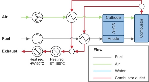
Figure 2‑1 Reference SOFC system
2.2 Methane system
For every fuel, the system is extended with the necessary components. All heat regeneration components are added to the exhaust stream in order of required heat quality. Methane is used to model the LNG system, since the composition of natural gas varies much globally. Moreover, most other experimental and simulation studies also use methane, which makes it more convenient for benchmark purposes. For the methane system (Figure 2‑2), water is heated and added at a steam to carbon ratio of 2.3 (molar) to prevent carbon deposition. A 20% adiabatic pre-reformer is used to reduce the stress on the fuel-catalyst. An extra heat exchanger is added to pre-heat the fuel before it enters the reformer and remaining heat after the hot water generation is used to evaporate the fuel. All heat exchangers are added to the exhaust stream in order of required heat quality.
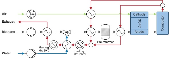
Figure 2‑2 Methane-fuelled SOFC system
2.3 Methanol system
Methanol is stored as a liquid at ambient temperature. The methanol is supplied with a pump and evaporated using remaining heat in the exhaust stream, see Figure 2‑3. Methanol decomposition and the water gas shift reaction fully convert methanol to water, hydrogen gas, carbon monoxide and carbon dioxide in the reformer. The heat in the exhaust stream is also used to supply heat to the reformer. Following, heat is used to for steam generation, hot water generation and finally to evaporate the methanol. Part of the generated steam is also fed to the methanol reformer.
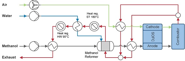
Figure 2‑3 Methanol-fuelled SOFC system
2.4 Diesel system
The diesel system (Figure 2‑4) is very similar to the methanol system. After being preheated, diesel is reformed in an allothermal reformer, see equation 3.1. Although, autothermal reforming is often considered in combination with SOFCs for being relatively compact in terms of size and weight (Ahemed and Krumpelt, 2001; Papadias et al., 2006), higher electric efficiencies can be reached with an allothermal reformer. Analogous to the methanol system, heat and steam are fed into the reformer. Here, hot water is generated after heating the diesel, due to differences in required heat quality.
2Cn Hm + n/2 O2+ nH2O → (n + m)H2 +2nCO (3.1)
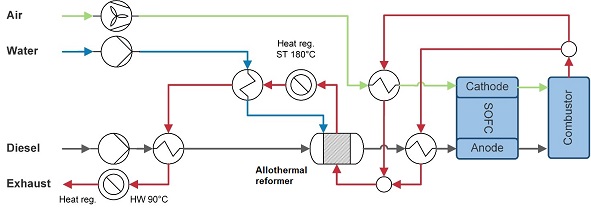
Figure 2‑4 Diesel-fuelled SOFC system
2.5 Ammonia system
Ammonia is stored cryogenically in cylindrical tanks at -33°C. The liquid ammonia evaporated, pre-heated, and fed directly into the SOFC, see Figure 2‑5. In the SOFC, the ammonia is internally cracked (endothermic reaction 3.2 with ΔH = 383 kJ/mol).
2NH3→ N2 +3H2 (3.2)
The remaining heat after steam and hot water generation is used to evaporate the ammonia.
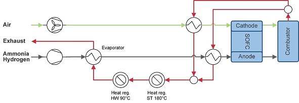
Figure 2‑5 Ammonia-fuelled or Hydrogen-fuelled SOFC system
2.6 Hydrogen system
Similar to the ammonia model, hydrogen is fed directly into the SOFC after evaporation and preheating from its liquid storage temperature of -253°, see Figure 2‑5.
3 Methods
The performance of the presented marine SOFC power plants is further investigated. The performance is expressed in electric efficiency and thermal efficiency, for which thermodynamic simulations are performed.
3.1 Thermodynamic modelling
A flow-sheet software (Cycle-Tempo) is used for the thermodynamic analysis of the fuel cell systems. Cycle Tempo contains models for the relevant fuel cell system components, such as pumps, compressors, evaporators, reformers, fuel cells, combustors, valves, and heat exchangers. Together, these components form a system matrix of mass and energy equations, which is used to calculate mass flows, pressures, temperatures, and compositions of all flows. The ideal gas law and no losses in piping are assumed. The fuel cell and combustor use a Gibbs free energy minimisation routine. In an internally reformed SOFC model, Cycle Tempo determines the equilibrium compositions of the inlet gas. From this equilibrium, the current flow and electrical power output are determined, where the internal temperature and pressures are assumed constant. Then the fuel cell parameters are calculated from the following current flow.
3.2 Thermodynamic simulations
Figure 3‑1 shows the methods for the simulation. First, the model of the SOFC is matched with a performance map for 60% and 40% -fuelled SOFC. With this performance map, the cell resistance and the cell area of the fuel cells are determined. The cell resistance and area are used as fixed input for the five presented SOFC systems. This simulation is used to obtain the results in the next section.
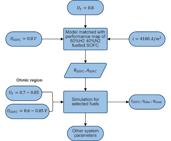
Figure 3‑1 Used method for thermodynamic simulations.
4 Efficiency comparison
Figure 4‑1 compares the efficiency and delivered AC power of the different SOFC systems. The results of electrical efficiency are in accordance with literature and theory regarding the theoretical efficiency of SOFC for the different fuels. Methane, diesel, and ammonia result in high electrical efficiency. The electrical efficiency of methanol and hydrogen is much lower.
The heat efficiency is mainly attributed to the amount of heat that was regenerated for hot water and saturated steam purposes and thus is very dependent on the temperature and mass flow of the flue gas after the burner and the defined final exhaust temperature. The diesel-fuelled SOFC system has the lowest heat efficiency. This can be explained by the high heat requirements for the reforming process. Ammonia results in the highest heat efficiency since there is much energy in the SOFC exhaust due to internal cracking. Moreover, a relatively small airflow results in high temperatures after the combustor. Although this overview compares heat efficiency, not all supplied heat is of the same quality. If heat is supplied at low temperature, it might not be usable for the saturated steam network. These results show that that from an energy efficiency perspective, the best candidate might depend on the electric and heat demand of the ship.
For the carbon-containing fuels (methane, methanol, and diesel), the power density and thus delivered power is significantly lower (yellow line in Figure 4‑1). Although methane has the highest electrical efficiency, the delivered power is 15% lower than when fuelled with ammonia or hydrogen, meaning more cells need to be installed to deliver the required power.
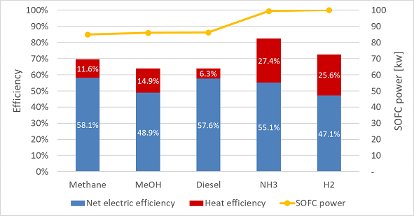
Figure 4‑1 Net electrical efficiency, heat efficiency and delivered SOFC power for the five selected fuels. Data is generated at nominal operation ( 0.8 V and UF =0.8).
Cruise ships often do not use all available heat from engines. Figure 4‑2 shows that all heat is not often used, and the heat demand rarely exceeds the produced heat in cruise ships. When the heat demand does exceed the produced heat, electric or fuel boilers are often employed. For diesel generators fuelled with fossil fuels, the waste heat recovery is limited by a minimum on the exhaust gas temperature. The waste heat recovery system is often design with a lower limit of the exhaust stream temperature around 200 °C to prevent formation of sulphuric acid, which means significant heat is still present in the final exhaust stream. Applying alternative, sulphur-free fuels enable heat regeneration up to a lower exhaust temperature.
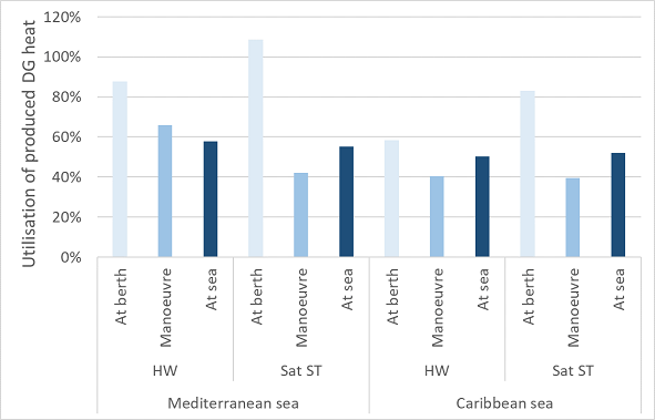
Figure 4‑2 Utilisation of produced diesel generator (DG) heat for the hot water (HW) net (90°C) and saturated steam (Sat ST) net (180°C and 9 bar).
It is of interest to investigate whether an SOFC power plant can also satisfy the heat profiles of a cruise ship. It is often assumed that a lot of heat is generated by SOFCs and that the heat demand is easily met because SOFCs operate at such high temperatures. However, much of the heat is already used in the SOFC system to pre-heat the fuel, air, and possibly water. In line with this comment, we found in the thermodynamic analysis that the flue gas does not have sufficient heat quality to generate steam for all the five considered systems. For instance, in the methanol, diesel, and hydrogen system, flue gas temperature after the heat exchangers was not high enough the generate steam at 180 °C (Table 4‑1). So, the rather high heat efficiencies of hydrogen and methanol presented in Figure 4‑1 cannot be fully exploited in cruise ships. In practice, this reduces the electric efficiency, because fuel or electric energy is needed for boilers to fulfil the steam demand.
Table 4‑1 Recovered heat for the five selected SOFC systems.
| SOFC system |
Heat recovered for saturated steam net [kW] |
Heat recovered for hot water net [kW] |
| Methane | 11.45 | 5.22 |
| Methanol |
0 |
24.40 |
| Diesel | 0 |
9.24 |
| Ammonia | 18.25 | 30.22 |
| Hydrogen | 0 |
52.17 |
5 Conclusion
This study compared the performance of a marine SOFC power plant for several fuels (methane, methanol, diesel, ammonia, and hydrogen). A thermodynamic analysis was performed to simulate the performance of the SOFC system for the five selected fuels. A reference model was established, which was extended with the necessary components for the different fuels. The highest electrical efficiency was found for methane (58.1%), followed by diesel (57.6%) and ammonia (55.1%). Further investigating the electric efficiencies concluded that the blower power is the largest contributor to the parasitic power and is a determining factor for the net electrical efficiency, especially for low oxygen utilisation rates. The carbon fuels (methane, methanol, and diesel) resulted in a relatively low heat efficiency and around 15% reduced power density. The heat quality in the methanol, diesel, and hydrogen system is insufficient for heat regeneration for the saturated steam net of the ship. In practice, this reduces the electric efficiency, because additional fuel or electric energy is needed to fulfil the steam demand. The highest total efficiency was found for the ammonia-fuelled SOFC system.
To improve the amount and quality of heat regeneration, cathode off-gas recycling (COG-R) is recommended (see full report), because high airflows and low oxygen utilisation were encountered. Especially for methanol and hydrogen big improvements were found by adding COG-R. Analysing the difference between the selected system without and with CAG-R resulted in similar net electrical efficiencies. Moreover, a large increase in quality and size of heat efficiency was found, due to a lower airflow requirement and higher temperature after combustor (up to 900 °C). This resulted in an increase in the total efficiency of 3.5% to 25.1%. The smaller airflow also resulted in a heat transfer decrease in the air pre-heater of 22% to 73%, consequently decreasing the size, weight, and cost of this heat exchanger.
Stay in touch with us!
#NAUTILUS_2020 #propulsionsystem #sustainableshipping #battery #fuelcell #cruiseships
***
⇒ Follow us on Twitter/LinkedIn to be on board.
Follow #NAUTILUS_2020
NAUTILUS is a short for Nautical Integrated Hybrid Energy System for Long-haul Cruise Ships.

This project has received funding from the European Union’s Horizon 2020 research and innovation program under grant agreement No 861647.